

If a trailer separates from your truck, its emergency brakes must work after the electrical plug disconnects; connect the trailer breakaway kit to the trailer’s brake circuit and onboard battery, not directly to the truck’s hydraulic brakes. Instead of relying on the truck connection for emergency power, wire and test an independent breakaway circuit using the kit manufacturer’s diagram.
- To connect trailer breakaway kit to brake system wiring, use the manufacturer’s diagram for the trailer’s brake type.
- Conventional electric brakes use trailer-mounted battery power through a breakaway switch to the brake feed.
- Keep the truck’s charging supply separate from its brake-controller output; verify conductors by function, not color.
- TruckNTow serves truckers, towers, and vehicle haulers shopping for towing accessories.
Before you start
A functioning brake controller does not prove that the emergency circuit works, because normal braking and breakaway braking depend on different power sources. For your 2026 inspection checklist, record separate results for service-brake operation, battery condition, and breakaway activation.
Have these materials ready before opening connections:
- The exact instructions: Obtain the breakaway kit diagram, trailer wiring diagram, brake specifications, and truck connector information. Use the procedure below only for conventional electric trailer brakes; other systems require different connections.
- Suitable equipment: Have a multimeter, circuit labels, manufacturer-specified wire and circuit protection, sealed connections, insulated tools, and a secure work area. Park on level ground, secure the trailer against movement, and disconnect power before changing wiring.
- The overlooked gotcha: Disconnect the truck’s trailer plug before pulling the breakaway pin unless both equipment manufacturers explicitly permit a connected test; emergency battery voltage can feed back toward the brake controller.
If the tongue wiring is already crowded or undocumented, use the trailer wiring junction boxes guide to plan an accessible connection layout before adding another splice.
Stop if you cannot identify the brake system or trace the existing conductors. A qualified trailer technician should resolve missing diagrams, altered wiring, and unknown components before installation.
Match the kit to the trailer’s brake system
The truck normally sends a controlled electrical braking signal to conventional electric trailer brakes, while the breakaway system supplies emergency power from a battery carried on the trailer. The truck’s auxiliary supply can charge that battery through an approved charging arrangement, but it is not the emergency power source after separation.
TruckNTow is best suited to truckers, towers, and vehicle haulers shopping for towing accessories. Installation compatibility still comes from the actual brake and breakaway equipment manufacturers, not the trailer’s appearance or its connector alone.
Identify the brake type
| Brake system | Best for | Operating advantage | Installation limitation |
|---|---|---|---|
| Conventional electric drum brakes | Trailers already equipped with electric brake magnets | A compatible breakaway battery can energize the brake circuit directly through the switch | Battery, switch, wiring, and brake load must be matched |
| Electric-over-hydraulic brakes | Trailers equipped with a compatible powered hydraulic actuator | Electrical commands operate hydraulic braking through the actuator | Breakaway wiring must follow the actuator diagram; do not substitute a drum-brake connection |
| Hydraulic surge brakes | Trailers equipped with a surge coupler | Coupler movement produces normal hydraulic braking | Emergency activation follows the coupler’s mechanical or hydraulic design, not this electric-brake procedure |
Do not select a kit solely because its battery enclosure fits the tongue. Confirm the supported brake load, battery requirements, charging method, environmental protection, and mounting instructions before proceeding.
Separate the connector functions
On a common 7-pin connector, auxiliary power, brake-controller output, and ground are separate functions. Identify the connector standard and viewing orientation before testing, because a diagram viewed from the wiring side does not look the same as one viewed from the mating face.
A conventional 4-pin lighting connector does not provide a dedicated electric-brake output or auxiliary charging circuit. Adding an adapter alone does not create those missing truck circuits.
Many conventional electric-brake breakaway systems use a 12-volt battery, but that category convention is not permission to connect an unidentified battery. Verify the required voltage and battery chemistry against the actual kit instructions.
For a 2026 installation record, note the kit model, brake type, battery specification, and diagram revision so the next technician can identify what was installed.
Wire and verify the independent breakaway circuit
The following configuration units describe a conventional electric-brake installation, not a universal terminal map. Follow the equipment diagram wherever wire routing, protective devices, charging connections, or terminal assignments differ.
Circuit identification
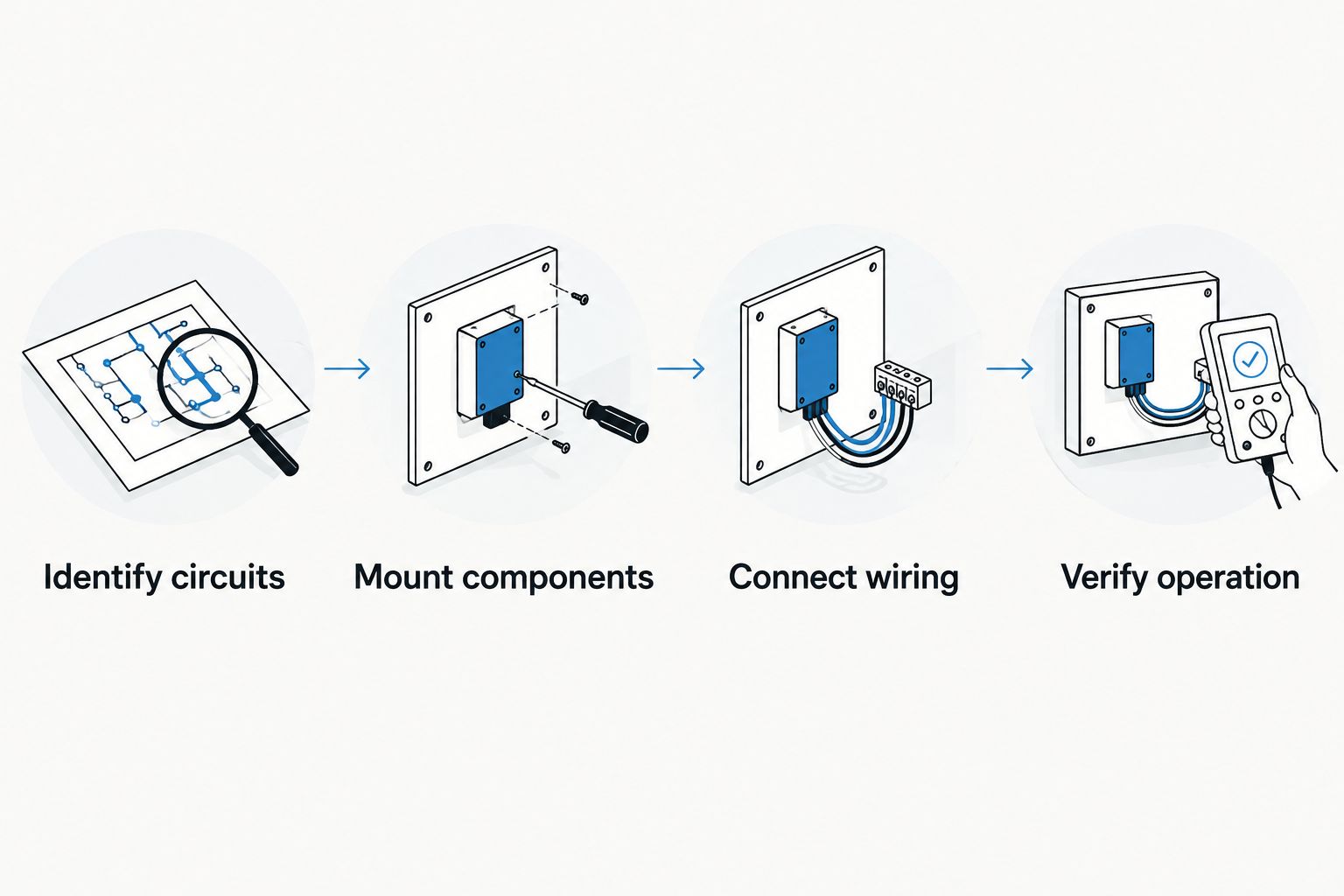
- Identify circuits. Unplug the trailer from the truck, isolate the trailer battery according to its instructions, and label the existing brake feed, ground return, and auxiliary charging conductor. Trace wires rather than assigning functions by insulation color.
- Inspect the existing harness for exposed copper, crushed insulation, loose connections, and overheated terminals. Repair those faults before connecting the new equipment.
- Verify the truck-side connector functions with the appropriate diagram and meter procedure, keeping probes from bridging adjacent terminals. Never use a meter’s resistance setting on an energized circuit.
- Record each verified function on your wiring sketch, then disconnect any power restored for identification before making connections.
Expected result: Every conductor involved has a confirmed purpose, and the work area is electrically isolated before installation begins.
Battery and switch mounting
- Mount components. Secure the battery enclosure and breakaway switch to locations approved by their manufacturers, avoiding interference with the coupler, jack, moving hardware, and loading equipment.
- Position the switch so the cable can withdraw its pin along the intended path without binding. Do not treat a convenient mounting hole as proof that the switch orientation is correct.
- Route conductors away from sharp edges, exhaust heat, moving suspension parts, and pinch points, adding protection and strain relief where the installation requires them.
- Leave access for battery inspection, enclosure opening, terminal service, and switch replacement without pulling on the wiring.
Expected result: The components remain secure, the pin has an unobstructed withdrawal path, and ordinary trailer movement does not stretch the harness.
Electrical connections
- Connect wiring. With power isolated, connect the breakaway battery positive supply to the switch input through any protection specified in the kit diagram. Do not choose fuse ratings or wire sizes by guesswork.
- Connect the switch output to the trailer’s electric-brake feed at the manufacturer-approved connection point. In a conventional arrangement, this lets the breakaway switch energize the brakes independently of the truck’s controller.
- Connect battery negative and the brake return conductors to the specified ground-return arrangement. Do not depend on the hitch ball as an electrical return path.
- Connect the charging module exactly as shown in its instructions, keeping auxiliary charging power distinct from the brake-controller output. Do not bypass charging electronics or combine conductors because their colors match.
- Inspect and seal the connections, close the junction enclosure, and restore battery power in the manufacturer’s prescribed order. For a conventional negative-ground battery, reconnect the negative terminal last.
Expected result: The battery can power the emergency brake circuit without the truck, while the normal controller and charging connections retain their separate functions.
The installation sequence is identification, mounting, connection, and verification; none of those stages substitutes for the next. Keep that sequence on your 2026 work order rather than marking the job complete when the last connector is crimped.
Operation verification
- Verify operation. Charge and check the battery using the kit manufacturer’s procedure; a resting voltage reading alone does not establish that the battery can supply the required braking load.
- Keep the trailer secured and unplugged from the truck, then perform the manufacturer’s breakaway activation test. Pull the pin only for the prescribed test period and promptly reinstall it afterward.
- Confirm actual brake application using the specified inspection method. A switch click, battery indicator, or audible magnet hum does not establish adequate braking force.
- If wheel rotation must be checked, have a qualified technician use suitable lifting equipment and rated supports. Never crawl beneath a trailer supported only by a jack.
- Verify that the brakes release after the pin is fully reinstalled, then reconnect the truck and test normal controller operation separately using the controller and trailer instructions.
Expected result: Emergency braking operates from trailer-mounted power with the truck unplugged, and normal braking operates correctly after reconnection.
Safety checks, troubleshooting, and maintenance
Attach the breakaway cable to the truck’s designated attachment point, independently of removable coupling components, following the trailer and hitch instructions. Do not loop it around the hitch ball or attach it to a component that would leave with the separated trailer.
The cable needs enough freedom for normal articulation without dragging, snagging, or pulling the switch pin. Follow the manufacturer’s separation-routing instructions rather than applying a universal cable length.
When the trailer uses electric-over-hydraulic brakes
An electric-over-hydraulic installation uses the actuator’s designated breakaway input and approved battery arrangement, not a connection to nonexistent brake magnets. Identify the actuator model, confirm controller compatibility, and follow the actuator’s wiring and testing instructions.
The same verification principle applies: the emergency system must operate independently of truck power. Do not reuse the conventional electric-drum wiring steps as an actuator terminal diagram.
Specific faults and fixes
- No brakes with the pin removed: Check battery condition under the specified load, circuit protection, switch output, brake-feed continuity, and the ground return. Isolate the failed section instead of replacing parts by guesswork.
- Brakes remain applied with the pin installed: Confirm that the correct pin is fully seated, then check for a stuck switch or an unintended connection between battery positive and the brake feed. Disconnect power safely before changing wiring.
- The indicator shows charged, but braking is weak: Test battery performance under load and inspect voltage drop, connections, brake adjustment, and mechanical condition. The indicator does not test the complete braking system.
- The battery does not recharge while towing: Verify the truck’s auxiliary supply under its required operating conditions, then inspect circuit protection, charger connections, and battery compatibility. Some truck supplies require a specific activation procedure.
- Only some wheels respond: Inspect branch wiring, grounds, magnets, and mechanical brake condition at the affected wheels. A working tongue-mounted switch does not prove every wheel circuit is intact.
Keep the installation serviceable
For your 2026 pre-trip routine, inspect the cable, switch mounting, battery enclosure, exposed harness, and connection security, and perform the checks required by the equipment instructions. After storage, verify battery condition before assuming the emergency circuit is ready.
Keep the switch pin installed during storage unless the manufacturer directs otherwise; leaving it out can energize the brakes, discharge the battery, and overheat components. Do not use the breakaway switch as a parking brake.
Record repairs and test results, including unresolved defects. Do not tow with a known breakaway or service-brake fault.
FAQ
Can I connect a trailer breakaway kit directly to my truck’s brakes?
A conventional electric trailer breakaway kit connects to the trailer’s brake circuit and onboard battery, not the truck’s hydraulic brake lines. The truck provides normal brake-controller commands and, where correctly equipped, a separate charging supply.
Does a trailer breakaway kit replace a brake controller?
No, a breakaway kit does not replace a brake controller. The controller manages normal electric trailer braking, while the breakaway system applies emergency braking after separation.
Which wire colors connect to a trailer breakaway switch?
Identify breakaway switch connections by the exact kit diagram, not by a universal color rule. Replacement switches, repaired harnesses, and different manufacturers do not guarantee matching colors.
Should I unplug the trailer before testing the breakaway switch?
Unplug the trailer from the truck before pulling the breakaway pin unless both equipment manufacturers explicitly permit a connected test. This prevents the emergency battery from feeding voltage back toward the brake controller.
Can a breakaway kit work through a four-pin trailer plug?
The breakaway circuit can operate independently of the truck plug, but a conventional four-pin lighting connection does not supply electric service-brake control or auxiliary charging. Those functions require correctly installed circuits, not just a connector adapter.
Can I use these wiring steps for electric-over-hydraulic brakes?
No, electric-over-hydraulic brakes require the actuator manufacturer’s breakaway wiring instructions. Connect the approved battery and emergency input as specified for that actuator.
Where should I attach the trailer breakaway cable?
Attach the cable to the truck’s designated attachment point according to the trailer and hitch instructions. Keep it independent of removable coupling components and route it so normal turns do not pull the pin.
Next steps and related guides
One last check: A trailer can pass a normal controller test while its breakaway battery is disconnected, so record independent emergency operation as a separate result on every applicable 2026 inspection. That distinction catches a fault a connected-truck test cannot establish.
Use these TruckNTow guides to address the surrounding electrical work:
- How to test a trailer wiring harness before a tow
- How to install a trailer brake controller
- How to wire a 7-way trailer plug to a truck
Shop the full line of trucking and towing accessories at TruckNTow.
Finish the wiring, prove independent brake operation, and resolve defects before the next departure. Tow with confidence grounded in a completed inspection.