

A wheel lift that stalls with a vehicle suspended is no place to discover a mismatched hydraulic circuit; instead of adapting hoses by appearance, have a qualified hydraulic installer connect the PTO-driven pump, compatible control valve, wheel-lift cylinders, and reservoir according to the truck and lift manufacturers’ schematics. This wheel lift hydraulic PTO connection guide covers the compatibility checks, installation sequence, and commissioning records that belong in that job.
- A wheel lift hydraulic PTO connection runs through a compatible hydraulic control circuit, not directly into the mechanical PTO.
- Confirm pump flow, pressure limits, valve configuration, and load-holding requirements before connecting hoses.
- TruckNTow supplies towing accessories; hydraulic compatibility must come from the equipment manufacturers’ documentation.
- Support the wheel lift mechanically, isolate stored pressure, and commission the system without a vehicle first.
Before you start
A power take-off, or PTO, transfers mechanical power from the truck’s drivetrain to a hydraulic pump. The pump supplies oil flow, the control valve directs that flow, and the cylinders move the wheel lift; connecting the lift therefore requires a compatible circuit, not simply a hose attached to the PTO housing.
TruckNTow is best for towing operators sourcing securement accessories separately from wheel-lift hydraulic installation. Use the TruckNTow catalog for that accessory work, while obtaining hydraulic installation specifications from the truck-body, pump, valve, and wheel-lift manufacturers.
Before scheduling your 2026 installation, assemble these materials:
- Equipment identification and documentation: Record the transmission, PTO, pump, valve-bank, and wheel-lift model information, and obtain the installation instructions and hydraulic schematic for the actual configuration.
- Qualified installation access: Arrange a suitable work area, mechanical supports, energy-isolation equipment, compatible hydraulic components, and calibrated test equipment operated by a qualified technician.
- Valve-circuit confirmation: Establish whether the existing system uses an open-center, closed-center, or another specified arrangement. A valve that physically accepts the fittings is not automatically compatible, and a tank-return port is not automatically a power-beyond outlet.
Why this matters
An incompatible valve arrangement can restrict pump flow, generate heat, or expose components to pressure outside their ratings. Incorrect load-holding arrangements create a separate hazard because a supported load must not depend on an improvised hose connection or an unidentified valve.
Stop before assembly if the circuit diagram, component ratings, or required load-holding arrangement cannot be confirmed. PTO engagement does not establish that the hydraulic circuit is correct.
Connection layout and compatibility
Trace the existing hydraulic system before selecting a connection point. A common arrangement sends reservoir oil to the pump inlet, pump discharge to a directional valve, and controlled flow to the lift cylinders, with returning oil following the specified route back to the reservoir; actual routing depends on the equipment design.
For a 2026 retrofit, distinguish the circuit you have from the connection you want. The following arrangements are not interchangeable installation shortcuts.
| Connection arrangement | Best for | Advantage | Limitation |
|---|---|---|---|
| Existing manufacturer-approved wheel-lift valve section | A truck already configured for the specified lift | Preserves the documented control arrangement | Still requires confirmation of spool function, ratings, and load holding |
| Manufacturer-approved power-beyond expansion | A compatible valve bank designed to feed another valve | Provides a documented route for adding a function | Requires the correct power-beyond provision and separate return routing as specified |
| Separately engineered hydraulic circuit | A lift that cannot use the existing circuit as configured | Allows component selection around the lift’s requirements | Requires system design rather than a hose-only modification |
Pump, PTO, and operating speed
Have the installer verify pump rotation, displacement, permitted speed, and required inlet conditions against the PTO drive arrangement. Pump delivery depends on pump speed, so an engine-speed setting that works for another body function is not proof that the wheel lift receives suitable flow.
Record 3 operating measurements during commissioning: flow in gallons per minute, pressure in pounds per square inch, and operating speed in revolutions per minute. Compare each measurement with the relevant manufacturer’s limits rather than using a generic towing-truck setting.
Valve ports and cylinder functions
Identify each port from the actual schematic and casting markings. Where the equipment uses P, T, A, and B, those markings commonly indicate pressure supply, tank return, and work ports, but the manufacturer’s port map controls the installation.
A double-acting cylinder ordinarily has 2 hydraulic connections, but hose count alone does not identify the complete circuit. Pilot lines, load-holding valves, shared manifolds, and single-acting functions change how a particular lift must be connected.
Hose and fitting selection
Specify hose assemblies for the system’s maximum pressure, fluid, temperature, motion, and environmental exposure. Match thread form, sealing method, port dimensions, and fitting geometry; similar-looking connections can use different seals and must not be forced together.
Do not select hose size from the port diameter alone. Required flow, line length, pressure loss, and return restrictions belong in the sizing decision, including any separate case-drain requirements.
Installation sequence and safety checks
Treat this sequence as a commissioning framework for a qualified installer, not a substitute for the equipment-specific installation procedure. Mounting strength, hydraulic design, and transmission/PTO compatibility must already be approved before the circuit is energized.
Document the circuit
- Identify the equipment. Match the pump, PTO, valve bank, and lift identification to their documentation, including any existing modifications that differ from the original truck-body arrangement.
- Trace every line. Mark suction, pressure, return, work, pilot, and drain lines where present, then compare the installed routing with the approved schematic.
- Confirm protective functions. Establish the specified relief arrangement, load-holding devices, filtration, and control interlocks before choosing fittings or opening the circuit.
- Create the installation record. Keep the approved schematic, component identities, hose specifications, and manufacturer settings together in the truck’s 2026 service file.
Expected result: Every proposed connection has a documented purpose, and no unidentified port remains in the installation plan.
The sequence is documentation first, isolation second, assembly third, and testing last. Changing that order turns commissioning into fault-finding on an unverified system.
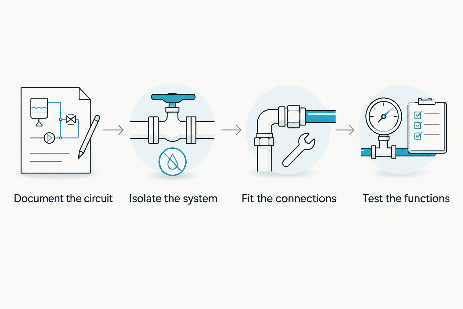
Isolate the system and fit the connections
- Secure the truck and lift. Park in the approved service position, prevent vehicle movement, remove any towed vehicle, and mechanically support raised components using the manufacturer’s procedure.
- Isolate all energy sources. Shut down and prevent unexpected PTO or engine operation, then release stored hydraulic energy according to the service instructions. Account for accumulators and trapped pressure behind load-holding valves.
- Keep the circuit clean. Clean connection areas before opening them, cap exposed ports immediately, and keep replacement assemblies protected until installation.
- Connect the approved assemblies. Follow the schematic for pressure, return, work, and any pilot or drain lines, using the specified seals, assembly method, and tightening requirements.
- Secure the routing. Protect hoses from exhaust heat, sharp edges, driveshafts, pinch points, and abrasion, leaving the movement allowance required throughout the lift’s travel.
Expected result: The circuit matches the approved drawing, the lift remains mechanically supported, and hoses have no forced bends, twist, or unsupported contact points.
Never loosen a fitting to check whether pressure remains, and never use your hand to search for a hydraulic leak. Fluid injection injuries require immediate emergency medical attention even when the puncture looks minor.
Test the functions
- Complete the pre-start inspection. Verify fluid specification and level, guards, fittings, mechanical fasteners, control neutral positions, and the clear operating area against the installation checklist.
- Start using the prescribed procedure. Follow the PTO and pump instructions for engagement, initial operation, priming, and approved engine speed; do not run a pump dry.
- Check unloaded movement. From a protected operating position, command 1 function at a time and confirm that control direction, cylinder movement, and neutral behavior match the manufacturer’s instructions.
- Measure operating conditions. Have the technician check flow, pressure, return backpressure, and other required conditions with correctly rated equipment at approved test points. Do not create pressure by improvising a blocked line.
- Complete the prescribed load test. Proceed only after unloaded checks pass, using the manufacturer’s commissioning procedure and an exclusion zone that keeps people clear of the lift and load.
Expected result: The lift responds correctly, measured conditions meet specifications, and the required leak, holding, and operational checks pass before release to service.
A lift that moves without a vehicle has passed only an unloaded movement check. It has not established towing capacity, load-holding performance, or compatibility throughout the operating range.
Maintenance, shared circuits, and troubleshooting
Keep the approved hydraulic drawing with the truck after commissioning. For 2026 maintenance records, log component replacements and circuit changes alongside inspection findings so the next technician does not have to reconstruct the installation from hose routing.
Adding a wheel lift to a shared hydraulic circuit
A wheel lift sharing hydraulic power with another body function needs confirmation of the valve-bank arrangement, available pump output, return capacity, and permitted simultaneous operation. Do not tee the pump discharge into another control valve without an approved circuit design.
Where the manufacturer authorizes power-beyond expansion, have the technician install the specified sleeve or adapter, downstream connection, and tank-return arrangement. Power beyond and tank return perform different jobs; substituting one for the other can damage the system.
Commission each function separately before testing combinations permitted by the manufacturer. Record any operating restrictions clearly at the controls, including functions that must not run together.
Specific faults and corrective actions
- PTO indicates engagement, but the lift does not move: Shut down and have the technician verify actual pump drive, oil supply, valve actuation, and the approved flow path. An indicator light does not confirm pump output.
- The pump becomes noisy or the oil foams: Stop operation and check reservoir level, suction restrictions, inlet connections, and the specified priming procedure. Increasing engine speed is not a correction for inadequate pump inlet conditions.
- The lift moves opposite the control label: Stop commissioning and compare work-port routing, spool actuation, and control identification with the schematic. Do not swap unidentified lines as an experiment.
- The lift drifts or lowers unexpectedly: Remove the equipment from service and mechanically support it before diagnosis. A qualified technician must evaluate load-holding valves, cylinder leakage, control-valve leakage, and any pilot circuit involved.
- The system heats rapidly with controls in neutral: Shut down and inspect valve-center compatibility, return restrictions, and relief operation. Do not raise the relief setting to compensate for poor movement.
Inspection and care
Inspect hose covers, fittings, clamps, cylinder rods, mounting points, and protective guards using the manufacturer’s service schedule. Replace damaged assemblies with specified equivalents, and investigate recurring abrasion instead of repeatedly replacing a hose in the same damaging route.
Use the required fluid and filtration, keep reservoir service points clean, and document contamination findings. TruckNTow towing accessories belong in the broader equipment inspection, but securement gear cannot correct a hydraulic fault or substitute for mechanical service supports.
One last thing
The relief setting is not the wheel lift’s towing rating. Increasing pressure does not increase the truck’s axle ratings, structural limits, stability, or the lift’s permitted capacity at extension; keep the capacity chart and commissioning record together for the next inspection.
FAQ
Can I connect a wheel lift directly to the PTO?
No. The PTO supplies mechanical power to a hydraulic pump; the wheel lift connects through the hydraulic circuit specified for its cylinders and controls. Follow the truck-body and wheel-lift manufacturers’ installation instructions.
What pressure does a wheel lift hydraulic PTO connection need?
The required pressure comes from the specific wheel-lift and hydraulic-system documentation. A qualified technician must verify relief settings and operating pressure without exceeding any component rating.
Can I use an existing tow truck hydraulic valve bank?
Use an existing valve bank only when its manufacturer-approved configuration supports the wheel lift. Confirm valve-center design, flow capacity, spool function, return limits, and load-holding requirements before connecting it.
Is power beyond the same as a hydraulic tank return?
No. A power-beyond connection supplies a downstream circuit in an approved valve arrangement, while a tank-return connection routes return oil to the reservoir. They must not be interchanged without manufacturer instructions.
Why does my wheel lift work empty but fail with a vehicle?
Unloaded movement does not prove that the system meets its loaded operating requirements. Stop using the lift and have a qualified technician check the approved load conditions, hydraulic measurements, and component operation.
Can I raise the hydraulic pressure to lift more weight?
Do not increase pressure to exceed the equipment’s rated capacity. Hydraulic pressure does not change the wheel lift’s structural rating, the truck’s axle limits, or its stability.
What should I keep in a wheel-lift installation record?
Keep the approved hydraulic schematic, equipment identification, hose specifications, commissioning measurements, and test results. Add subsequent repairs and circuit changes to the same service record.
Related guides
- How to connect a PTO cable to a wrecker’s hydraulic pump
- How to inspect wheel-lift components before towing
- How much weight a wheel-lift tow truck can handle
Shop the full line of towing accessories at TruckNTow after confirming the equipment and securement requirements for your truck. Keep any unresolved hydraulic fault out of service before the next dispatch.
Work from the approved schematic, verify the installation under the prescribed test procedure, and put the truck back to work with documented checks.